Optical elements
Module oes defines a generic optical element in
class OE. Its methods serve mainly for propagating the beam downstream
the beamline. This is done in the following sequence: for each ray transform
the beam from global to local coordinate system, find the intersection point
with the OE surface, define the corresponding state of the ray, calculate the
new direction, rotate the coherency matrix to the local s-p basis, calculate
reflectivity or transmittivity and apply it to the coherency matrix, rotate the
coherency matrix back and transform the beam from local to the global
coordinate system.
Module oes defines also several other optical
elements with various geometries.
The main base class for an optical element. |
|
Base class for a diced optical element. |
|
Simply bent reflective crystal. |
|
Ground-bent (Johansson) reflective crystal. |
|
2D bent reflective crystal. |
|
Ground-2D-bent (Johansson) reflective optical element. |
|
Ground-2D-bent reflective optical element with 4 independent radii: meridional and sagittal for the surface (Rm and Rs) and the atomic planes (RmBragg and RsBragg). |
|
Diced version of |
|
Diced version of |
|
Flat Laue plate. |
|
Simply bent reflective optical element in Laue geometry (duMond). |
|
Parabolically bent reflective optical element in Laue geometry. |
|
Ground-bent reflective optical element in Laue geometry. |
|
Spherically bent reflective optical element in Laue geometry. |
|
Cylindrical parabolic mirror. |
|
Toroidal mirror. |
|
Elliptical mirror as a parametric surface. |
|
Parabolical mirror as a parametric surface. |
|
Hyperbolic mirror as a parametric surface. |
|
Conical mirror with its base parallel to the side of the cone. |
|
Double Crystal Monochromator with flat crystals. |
|
DCM with horizontally focusing 2nd crystal. |
|
Body with two surfaces. |
|
Refractive lens or a stack of lenses (CRL) with one side as paraboloid and the other one flat. |
|
Refractive lens or a stack of lenses (CRL) with one side as parabolic cylinder and the other one flat. |
|
Refractive lens or a stack of lenses (CRL) with two equal paraboloids from both sides. |
|
Refractive lens or a stack of lenses (CRL) with two equal parabolic cylinders from both sides. |
|
Base class for parametric surfaces of revolution. |
|
Paraboloid of revolution or Mirror Lens. |
|
Ellipsoid of revolution or Mirror Lens. |
|
Hyperboloid of revolution or Mirror Lens. |
|
Circular Fresnel Zone Plate placed normally to incoming beam, as described in X-Ray Data Booklet, Section 4.4. |
|
General Fresnel Zone Plate, where the zones are determined by two foci and the surface shape of the OE. |
|
Grating of triangular shape given by two angles. |
|
Grating of rectangular profile. |
|
Grating of rectangular profile with variable period. |
|
Optical element defined by an STL mesh. |
- class xrt.backends.raycing.oes.OE
The main base class for an optical element. It implements a generic flat mirror, crystal, multilayer or grating.
- __init__(bl=None, name='', center=[0, 0, 0], pitch=0, roll=0, yaw=0, positionRoll=0, rotationSequence='RzRyRx', extraPitch=0, extraRoll=0, extraYaw=0, extraRotationSequence='RzRyRx', alarmLevel=None, surface=None, material=None, figureError=None, alpha=None, limPhysX=[-1000.0, 1000.0], limOptX=None, limPhysY=[-1000.0, 1000.0], limOptY=None, isParametric=False, shape='rect', gratingDensity=None, order=None, shouldCheckCenter=False, targetOpenCL=None, precisionOpenCL='float32', **kwargs)
- bl: instance of
BeamLine Container for beamline elements. Optical elements are added to its oes list.
- name: str
User-specified name, occasionally used for diagnostics output.
- center: 3-sequence of floats
3D point in global system. Any two coordinates can be ‘auto’ for automatic alignment.
- pitch, roll, yaw: floats
Rotations Rx, Ry, Rz, correspondingly, defined in the local system. If the material belongs to Crystal, pitch can be calculated automatically if alignment energy is given as an energy string such as ‘8000 eV’ or ‘8 keV’. If ‘auto’, the alignment energy will be taken from beamLine.alignE. The legacy single element list syntax [energy] is still accepted but deprecated.
- positionRoll: float
A global roll used for putting the OE upside down (=np.pi) or at horizontal deflection (=[-]np.pi/2). This parameter does the same rotation as roll. It is introduced for holding large angles, as π or π/2 whereas roll is meant for smaller [mis]alignment angles.
- rotationSequence: str, any combination of ‘Rx’, ‘Ry’ and ‘Rz’
Gives the sequence of rotations of the OE around the local axes. The sequence is read from left to right (do not consider it as an operator). When rotations are more than one, the final position of the optical element depends on this parameter.
- extraPitch, extraRoll, extraYaw, extraRotationSequence:
Similar to pitch, roll, yaw, rotationSequence but applied after them. This is sometimes necessary because rotations do not commute. The extra angles were introduced for easier misalignment after the initial positioning of the OE.
- alarmLevel: float or None
Allowed fraction of incident rays to be absorbed by OE. If exceeded, an alarm output is printed in the console.
- surface: None or sequence of str
If there are several optical surfaces, such as metalized stripes on a mirror, these are listed here as names; then also the optical limits must all be given by sequences of the same length if not None.
- material: None or sequence of material objects
The material(s) must have
get_amplitude()orget_refractive_index()method. If not None, must correspond to surface. If None, the reflectivities are equal to 1.
figureError: None or FigureError object.
- alpha: float
Asymmetry angle for a crystal OE (rad). Positive sign is for the atomic planes’ normal looking towards positive y.
- limPhysX and limPhysY: [min, max] where min, max are
floats or sequences of floats Physical dimension = local coordinate of the corresponding edge. Can be given by sequences of the length of surface. You do not have to provide the limits, although they may help in finding intersection points, especially for (strongly) curved surfaces.
- limOptX and limOptY: [min, max] where min, max are
floats or sequences of floats Optical dimension = local coordinate of the corresponding edge. Useful when the optical surface is smaller than the whole surface, e.g. for metalized stripes on a mirror.
- isParametric: bool
If True, the OE is defined by parametric equations rather than by a surface function z(x, y). A parametric representation is particularly useful for describing closed surfaces, such as capillaries. The user must provide the transformation functions
param_to_xyz()andxyz_to_param(), which map between the local Cartesian coordinates (x, y, z) and the parametric coordinates (s, phi, r), as well as the surface function local_r(s, phi). The exact meaning of the parameters (s, phi, r) is defined entirely by these user-supplied functions. For example, they may be interpreted as generalized cylindrical coordinates, where s is a longitudinal coordinate along a three-dimensional curve, while phi and r are polar coordinates in planes normal to the curve and intersecting it at position s. The classSurfaceOfRevolutionprovides an example implementation of these transformation functions and represents a useful class of parametric surfaces.The methods
local_n()(surface normal) andlocal_g()(grating vector, if applicable) return three-dimensional vectors in the local Cartesian coordinate system. In the parametric case, however, their coordinate arguments are (s, phi) rather than (x, y).The limits [limPhysX, limOptX] and [limPhysY, limOptY] continue to define the physical and optical boundaries in the local x and y coordinates, respectively. In addition, local beam footprints contain arrays of the parametric coordinates s, phi and r.
- shape: str or list of [x, y] pairs
The shape of OE. Supported: ‘rect’, ‘round’ or a list of [x, y] pairs for an arbitrary shape. shape refers to the geometric shape of the XY projection. ‘round’ shape makes a circular disk, not a capillary optical element. The latter can be made as a parametric surface, see e.g.
SurfaceOfRevolutionorEllipticalMirrorParam.- gratingDensity: None or list
If material kind = ‘grating’, its density can be defined as list [axis, ρ0, P0, P1, …], where ρ0 is the constant line density in inverse mm, P0 – Pn are polynom coefficients defining the line density variation, so that for a given axis
\[\rho_x = \rho_0\cdot(P_0 + 2 P_1 x + 3 P_2 x^2 + ...).\]Example: [‘y’, 800, 1] for the grating with constant spacing along the ‘y’ direction; [‘y’, 1200, 1, 1e-6, 3.1e-7] for a VLS grating. The length of the list determines the polynomial order.
Note
Redefining
local_g()is the most flexible way to define a VLS grating.- order: int or sequence of ints
The order(s) of grating, FZP or Bragg-Fresnel diffraction.
- shouldCheckCenter: bool
This is a leagcy parameter designed to work together with alignment stages – classes in module
stages– which modify the orientation of an optical element. if True, invokes checkCenter method for checking whether the oe center lies on the original beam line. checkCenter implies vertical deflection and ignores any difference in height. You should override this method for OEs of horizontal deflection.- targetOpenCL: None, str, 2-tuple or tuple of 2-tuples
pyopencl can accelerate the search for the intersections of rays with the OE. If pyopencl is used, targetOpenCL is a tuple (iPlatform, iDevice) of indices in the lists cl.get_platforms() and platform.get_devices(), see the section Calculations on GPU. None, if pyopencl is not wanted. Ignored if pyopencl is not installed.
- precisionOpenCL: ‘float32’ or ‘float64’, only for GPU.
Single precision (float32) should be enough. So far, we do not see any example where double precision is required. The calculations with double precision are much slower. Double precision may be unavailable on your system.
- bl: instance of
- local_g(x, y, rho=-100.0)
For a grating, gives the local reciprocal groove vector (without 2pi!) in 1/mm at (x, y) position. The vector must lie on the surface, i.e. be orthogonal to the normal. Typically is overridden in the derived classes or defined in Material class. Returns a 3-tuple of floats or of arrays of the length of x and y.
Note
The sign of the returned vector depends on the user’s definition of the diffraction order sign.
- local_n(x, y)
Determines the normal vector of OE at (x, y) position. Typically is overridden in the derived classes. If OE is an asymmetric crystal, local_n must return 2 normals as a 6-sequence: the 1st one of the atomic planes and the 2nd one of the surface. Note the order!
If isParametric in the constructor is True,
local_n()still returns 3D vector(s) in local xyz space but now the two input coordinate parameters are s and phi.The result is a 3-tuple or a 6-tuple. Each element is either a scalar or an array of the length of x and y.
- local_n_distorted(x, y)
Distortion to the local normal. If isParametric in the constructor is True, the input arrays are understood as (s, phi).
Distortion can be given in two ways and is signaled by the length of the returned tuple:
As d_pitch and d_roll rotation angles of the normal (i.e. rotations Rx and Ry). A tuple of the two arrays must be returned. This option is also suitable for parametric coordinates because the two rotations will be around Cartesian axes and the local normal (local_n) is also a 3D vector in local xyz space.
As a 3D vector that will be added to the local normal calculated at the same coordinates. The returned vector can have any length, not necessarily unity. As for local_n, the 3D vector is in local xyz space even for a parametric surface. The resulted vector local_n + local_n_distorted will be normalized internally before calculating the reflected beam direction. A tuple of 3 arrays must be returned.
- local_z(x, y)
Determines the surface of OE at (x, y) position. Typically is overridden in the derived classes. Must return either a scalar or an array of the length of x and y.
- multiple_reflect(beam=None, maxReflections=1000, needElevationMap=False, returnLocalAbsorbed=None)
Does the same as
reflect()but with up to maxReflections reflection on the same surface.The returned beam has additional fields: nRefl for the number of reflections, elevationD for the maximum elevation distance between the rays and the surface as the ray travels between the impact points, elevationX, elevationY, elevationZ for the coordinates of the maximum elevation points.
- returnLocalAbsorbed: None or int
–DEPRECATED–
- prepare_wave(prevOE, nrays, shape='auto', area='auto', rw=None)
Creates the beam arrays used in wave diffraction calculations. prevOE is the diffracting element: a descendant from
OE,RectangularApertureorRoundAperture. nrays: if int, specifies the number of randomly distributed samples the surface withinself.limPhysXlimits; if 2-tuple of ints, specifies (nx, ny) sizes of a uniform mesh of samples; if 2-tuple of arrays, specifies the (x, y) positions.
- reflect(beam=None, needLocal=True, noIntersectionSearch=False, returnLocalAbsorbed=None)
Returns the reflected or transmitted beam as \(\vec{out}\) in global and local (if needLocal is true) systems.
Mirror [wikiSnell]:
\[\begin{split}\vec{out}_{\rm reflect} &= \vec{in} + 2\cos{\theta_1}\vec{n}\\ \vec{out}_{\rm refract} &= \frac{n_1}{n_2}\vec{in} + \left(\frac{n_1}{n_2}\cos{\theta_1} - \cos{\theta_2}\right)\vec{n},\end{split}\]where
\[\begin{split}\cos{\theta_1} &= -\vec{n}\cdot\vec{in}\\ \cos{\theta_2} &= sign(\cos{\theta_1})\sqrt{1 - \left(\frac{n_1}{n_2}\right)^2\left(1-\cos^2{\theta_1}\right)}.\end{split}\]Grating or FZP [SpencerMurty]:
For the reciprocal grating vector \(\vec{g}\) and the \(m\)th diffraction order:
\[\vec{out} = \vec{in} - dn\vec{n} + \vec{g}m\lambda\]where
\[dn = -\cos{\theta_1} \pm \sqrt{\cos^2{\theta_1} - 2(\vec{g}\cdot\vec{in})m\lambda - \vec{g}^2 m^2\lambda^2}\]Crystal [SanchezDelRioCerrina]:
Crystal (generally asymmetrically cut) is considered a grating with the reciprocal grating vector equal to
\[\vec{g} = \left(\vec{n_\vec{H}} - (\vec{n_\vec{H}}\cdot\vec{n})\vec{n})\right) / d_\vec{H}.\]Note that \(\vec{g}\) is along the line of the intersection of the crystal surface with the plane formed by the two normals \(\vec{n_\vec{H}}\) and \(\vec{n}\) and its length is \(|\vec{g}|=\sin{\alpha}/d_\vec{H}\), with \(\alpha\) being the asymmetry angle.
[SpencerMurty]G. H. Spencer and M. V. R. K. Murty, J. Opt. Soc. Am. 52 (1962) 672.
[SanchezDelRioCerrina]M. Sánchez del Río and F. Cerrina, Rev. Sci. Instrum. 63 (1992) 936.
- needLocal: bool
Script-only option. If False, avoids separate local-beam copies when only the global output is needed. The return tuple keeps the same length, but its local outputs must not be used as local-coordinate beams. xrtQook does not expose this option and ignores its value when importing layouts, using the default True.
- returnLocalAbsorbed: None or int
–DEPRECATED–
- noIntersectionSearch: bool
Used in wave propagation, normally should be False. Certainly should be False if the OE is distorted or OE is parametric.
- class xrt.backends.raycing.oes.DicedOE(OE)
Base class for a diced optical element. It implements a flat diced mirror.
- __init__(*args, **kwargs)
- dxFacet, dyFacet: float
Size of the facets.
- dxGap, dyGat: float
Width of the gap between facets.
- facet_center_n(x, y)
Surface normal or (Bragg normal and surface normal).
- facet_center_z(x, y)
Z of the facet centers at (x, y).
- facet_delta_n(u, v)
Local surface normal (always without Bragg normal!) in the facet coordinates. In the asymmetry case the lattice normal is taken as constant over the facet and is given by
facet_center_n().
- facet_delta_z(u, v)
Local Z in the facet coordinates.
- class xrt.backends.raycing.oes.JohannCylinder(OE)
Simply bent reflective crystal.
- __init__(*args, **kwargs)
- Rm: float
Meridional radius.
- crossSection: str
Determines the bending shape: either ‘circular’ or ‘parabolic’.
- class xrt.backends.raycing.oes.JohanssonCylinder(JohannCylinder)
Ground-bent (Johansson) reflective crystal.
- class xrt.backends.raycing.oes.JohannToroid(OE)
2D bent reflective crystal.
- __init__(*args, **kwargs)
- Rm and Rs: float
Meridional and sagittal radii. Rs is set equal to Rm if None.
- class xrt.backends.raycing.oes.JohanssonToroid(JohannToroid)
Ground-2D-bent (Johansson) reflective optical element.
- class xrt.backends.raycing.oes.GeneralBraggToroid(JohannToroid)
Ground-2D-bent reflective optical element with 4 independent radii: meridional and sagittal for the surface (Rm and Rs) and the atomic planes (RmBragg and RsBragg).
- class xrt.backends.raycing.oes.DicedJohannToroid(DicedOE, JohannToroid)
Diced version of
JohannToroid.
- class xrt.backends.raycing.oes.DicedJohanssonToroid(DicedJohannToroid, JohanssonToroid)
Diced version of
JohanssonToroid.
- class xrt.backends.raycing.oes.LauePlate(OE)
Flat Laue plate. The thickness is defined in its material part.
- class xrt.backends.raycing.oes.BentLaueCylinder(OE)
Simply bent reflective optical element in Laue geometry (duMond). This element supports volumetric diffraction model, if corresponding parameter is enabled in the assigned material.
- __init__(*args, **kwargs)
- R: float or 2-tuple.
Meridional radius. Can be given as (p, q) for automatic calculation based the “Coddington” equations.
- crossSection: str
Determines the bending shape: either ‘circular’ or ‘parabolic’.
- class xrt.backends.raycing.oes.BentLaue2D(OE)
Parabolically bent reflective optical element in Laue geometry. Meridional and sagittal radii (Rm, Rs) can be defined independently and have same or opposite sign, representing concave (+, +), convex (-, -) or saddle (+, -) shaped profile. This element supports volumetric diffraction model, if corresponding parameter is enabled in the assigned material.
- __init__(*args, **kwargs)
- Rm: float or 2-tuple.
Meridional bending radius.
- Rs: float or 2-tuple.
Sagittal radius.
- class xrt.backends.raycing.oes.GroundBentLaueCylinder(BentLaueCylinder)
Ground-bent reflective optical element in Laue geometry.
- class xrt.backends.raycing.oes.BentLaueSphere(BentLaueCylinder)
Spherically bent reflective optical element in Laue geometry.
- class xrt.backends.raycing.oes.BentFlatMirror(OE)
Cylindrical parabolic mirror. Exemplifies inclusion of a new parameter (here, R) without the need of explicit repetition of all the parameters of the parent class.
- class xrt.backends.raycing.oes.ToroidMirror(OE)
Toroidal mirror. Exemplifies inclusion of new parameters (here, R and r) without the need of explicit repetition of all the parameters of the parent class.
- class xrt.backends.raycing.oes.EllipticalMirrorParam(OE)
Elliptical mirror as a parametric surface. The parameterization is the following: s - is local coordinate along the major axis with origin at the ellipse center. phi and r are local polar coordinates in planes normal to the major axis at every point s. The polar axis is upwards.
The center of this OE lies on the mirror surface and its pitch is Rx at this point.
If isCylindrical is True (default is False), the figure is an elliptical cylinder being flat in the lateral direction, otherwise it is an ellipsoid of revolution around the major axis.
If isClosed is True (default is False), the mirror is a complete surface of revolution. Otherwise the mirror is open, i.e. only its lower half is effective. If you want a closed mirror, compare this OE with
EllipsoidCapillaryMirrorthat can produce the same surface, just with another meaning of center and pitch parameters.Note
If the mirror is a closed surface, pitch should still be non-zero even if the major axis lies on the optical axis. A center must be defined somewhere on the surface and pitch is referred to that point.
The user supplies two foci either by focal distances p and q (both are positive distances from the mirror center to the focal points) or as f1 and f2 points in the global coordinate system (3-sequences). Any combination of (p or f1) and (q or f2) is allowed. If p is supplied, not f1, the incoming optical axis is assumed to be along the global Y axis. For a general orientation of the ellipse axes, f1 or pAxis – the p arm direction in global coordinates – should be supplied.
While either focal arm is missing or cannot yet be resolved, the OE behaves as a flat mirror. The elliptical surface and diagnostics are restored automatically when the configuration becomes complete.
Note
Any of p, q, f1, f2 or pAxis can be set as instance attributes of this mirror object; the ellipse parameters will be recalculated automatically.
Values of the ellipse semi-major and semi-minor axes lengths can be accessed after init as ellipseA and ellipseB respectively.
The usage is exemplified in test_param_mirror.py and test_ellipsoid_tube_mirror.py. Both test scripts can produce a 3D view by xrtGlow if a corresponding option at the top of the script is enabled.
- __init__(*args, **kwargs)
- p and q: float
p and q arms of the mirror, both are positive.
- f1 and f2: 3-sequence
Focal points in the global coordinate system. Alternatives for, correspondingly, p and q.
- pAxis: 3-sequence
Used with p, the p arm direction in global coordinates, defaults to the global Y axis.
- class xrt.backends.raycing.oes.ParabolicalMirrorParam(EllipticalMirrorParam)
Parabolical mirror as a parametric surface. The parameterization is the following: s - is local coordinate along the paraboloid axis with origin at the focus. phi and r are local polar coordinates in planes normal to the axis at every point s. The polar axis is upwards.
The user supplies one (and only one) focal distance p or q as a positive value. Alternatively, instead of p one can specify f1 (3-sequence) as a 3D point in the global coordinate system and instead of q – f2. If p or q is supplied, the paraboloid axis isassumed to be along the global Y axis, otherwise supply parabolaAxis as a vector in global coordinates.
If isCylindrical is True, the figure is an parabolical cylinder, otherwise it is a paraboloid of revolution around the major axis.
If isClosed is True (default is False), the mirror is a complete surface of revolution. Otherwise the mirror is open, i.e. only its lower half is effective. If you want a closed mirror, compare this OE with
ParaboloidCapillaryMirrorthat can produce the same surface, just with another meaning of center and pitch parameters.While the focal arm is missing, ambiguous or cannot yet be resolved, the OE behaves as a flat mirror. The parabolic surface and diagnostics are restored automatically when the configuration becomes valid.
Note
Any of p, q, f1, f2 or parabolaAxis can be set as instance attributes of this mirror object; the ellipsoid parameters will be recalculated automatically.
The usage is exemplified in test_param_mirror.py.
- __init__(*args, **kwargs)
- p or q: float
p and q arms of the mirror, both are positive. One and only one of them must be given.
- f1 and f2: 3-sequence
Focal points in the global coordinate system. Alternatives for, correspondingly, p and q. Only one of them must be given.
- parabolaAxis: 3-sequence
Used with p or q, the parabola axis in global coordinates, defaults to the global Y axis.
- class xrt.backends.raycing.oes.HyperbolicMirrorParam(OE)
Hyperbolic mirror as a parametric surface. The parameterization is the following: s - is local coordinate along the major axis with origin at the hyperbola center. phi and r are local polar coordinates in planes normal to the major axis at every point s. The polar axis is upwards.
Unlike EllipticalMirrorParam, reflective is the outer surface by default. If the inner surface is wanted, the instance variable invertNormal should be set equal to 1 after the class instantiation (alternatively, change it in a subclass).
Note
In both cases – outer or inner surface – foci f1 and f2 are numbered in the sense of propagation direction: from f1 to the mirror and then to imaginary focus (i.e. away from the focus) f2 after the reflection. In the outer case, f1 is the farther focus, while in the inner case it is the closer focus. See the example test_param_mirror.py, also in 3D.
The center of this OE lies on the mirror surface and its pitch is Rx at this point.
If isCylindrical is True (default is False), the figure is a hyperbolic cylinder being flat in the lateral direction, otherwise it is a hyperboloid of revolution around the major axis.
If isClosed is True (default is False), the mirror is a complete surface of revolution. Otherwise the mirror is open, i.e. only its one half is effective. If you want a closed mirror, compare this OE with
HyperboloidCapillaryMirrorthat can produce the same surface, just with another meaning of center and pitch parameters.Note
If the mirror is a closed surface, pitch should still be non-zero even if the major axis lies on the optical axis. A center must be defined somewhere on the surface and pitch is referred to that point.
The user supplies two foci either by focal distances p and q (both are positive distances from the mirror center to the focal points) or as f1 and f2 points in the global coordinate system (3-sequences). Any combination of (p or f1) and (q or f2) is allowed. If p is supplied, not f1, the incoming optical axis is assumed to be along the global Y axis. For a general orientation of the hyperbola axes f1 or pAxis – the p arm direction in global coordinates – should be supplied.
While either focal arm is missing or cannot yet be resolved, the OE behaves as a flat mirror. The hyperbolic surface and diagnostics are restored automatically when the configuration becomes complete.
Note
Any of p, q, f1, f2 or pAxis can be set as instance attributes of this mirror object; the hyperbola parameters will be recalculated automatically.
Values of the hyperbola semi-major and semi-minor axes lengths can be accessed after init as hyperbolaA and hyperbolaB respectively.
The usage is exemplified in test_param_mirror.py and test_hyperboloid_tube_mirror.py. Both test scripts can produce a 3D view by xrtGlow if a corresponding option at the top of the script is enabled.
- __init__(*args, **kwargs)
- p and q: float
p and q arms of the mirror – positive distances from the mirror center to the foci.
- f1 and f2: 3-sequence
Focal points in the global coordinate system. Alternatives for, correspondingly, p and q.
- pAxis: 3-sequence
Used with p, the p arm direction in global coordinates, defaults to the global Y axis.
- class xrt.backends.raycing.oes.ConicalMirror(OE)
Conical mirror with its base parallel to the side of the cone.
- __init__(*args, **kwargs)
- L0: float
Distance from the center of the mirror to the vertex of the cone. This distance is measured along the surface, NOT along the axis.
- theta: float
Opening angle of the cone (axis to surface) in radians.
- class xrt.backends.raycing.oes.DCM(OE)
Double Crystal Monochromator with flat crystals.
- __init__(*args, **kwargs)
- bragg: float, str, list
Bragg angle in rad. Can be calculated automatically if alignment energy is given as an energy string such as ‘8000 eV’ or ‘8 keV’. If ‘auto’, the alignment energy will be taken from beamLine.alignE. The legacy single element list syntax [energy] is still accepted but deprecated.
- braggOffset: float
Bragg angle offset in rad.
- cryst1roll, cryst2roll, cryst2pitch, cryst2finePitch: float
Misalignment angles in rad.
- cryst2perpTransl, cryst2longTransl: float
perpendicular and longitudinal translations of the 2nd crystal in respect to the 1st one.
- limPhysX2, limPhysY2, limOptX2, limOptY2, material2:
refer to the 2nd crystal and are similar to the same parameters of the parent class
OEwithout the trailing “2”.- fixedOffset: float
Offset between the incoming and outcoming beams in mm. If not None or zero the value of cryst2perpTransl is replaced by fixedOffset/2/cos(bragg)
- double_reflect(beam=None, needLocal=True, fromVacuum1=True, fromVacuum2=True, returnLocalAbsorbed=None)
Returns the reflected beam in global and two local (if needLocal is true) systems.
- needLocal: bool
Script-only option. If False, avoids separate local-beam copies when only the global output is needed. The return tuple keeps the same length, but its local outputs must not be used as local-coordinate beams. xrtQook does not expose this option and ignores its value when importing layouts, using the default True.
- returnLocalAbsorbed: None or int
–DEPRECATED–
- class xrt.backends.raycing.oes.DCMwithSagittalFocusing(DCM)
DCM with horizontally focusing 2nd crystal.
- __init__(*args, **kwargs)
Assume Bragg planes and physical surface planes are parallel (no miscut angle).
- Rs: float
Sagittal radius of second crystal.
- class xrt.backends.raycing.oes.Plate(DCM)
Body with two surfaces. Derived from
DCMbecause it also has two interfaces but the parameters referring to the 2nd crystal are ignored.- __init__(*args, **kwargs)
- t: float
Thickness in mm.
- wedgeAngle: float
Relative angular misorientation of the back plane.
- double_refract(beam=None, needLocal=True, returnLocalAbsorbed=None)
Returns the refracted beam in global and two local (if needLocal is true) systems.
- needLocal: bool
Script-only option. If False, avoids separate local-beam copies when only the global output is needed. The return tuple keeps the same length, but its local outputs must not be used as local-coordinate beams. xrtQook does not expose this option and ignores its value when importing layouts, using the default True.
- returnLocalAbsorbed: None, int
–DEPRECATED–
- class xrt.backends.raycing.oes.ParaboloidFlatLens(Plate)
Refractive lens or a stack of lenses (CRL) with one side as paraboloid and the other one flat.
- __init__(*args, **kwargs)
- focus: float or 2-tuple (focalDistance, E)
The focal distance of the of paraboloid in mm. It can also be calculated automatically for focalDistance at energy E. In this case, nCRL must be an integer. The paraboloid is then defined by the equation:
\[z = (x^2 + y^2) / (4 * \mathit{focus})\]Note
This is not the focal distance of the lens but of the parabola! The former also depends on the refractive index. focus is only a shape parameter!
- pitch: float
the default value is set to π/2, i.e. to normal incidence.
- zmax: float
If given, limits the z coordinate; the object becomes then a plate of the thickness zmax + t with a paraboloid hole at the origin.
- nCRL: int or 2-tuple (focalDistance, E)
If used as CRL (a stack of several lenslets), the number of the lenslets nCRL is either given by the user directly or calculated for focalDistance at energy E and then rounded. The lenses are stacked along the local [0, 0, -1] direction with the step equal to zmax + t for curved-flat lenses or 2*zmax + t for double curved lenses. For propagation with nCRL > 1 please use
multiple_refract().
- class xrt.backends.raycing.oes.ParabolicCylinderFlatLens(ParaboloidFlatLens)
Refractive lens or a stack of lenses (CRL) with one side as parabolic cylinder and the other one flat. The lenslets focalize in one direction and they are flat in their local x direction and curved in the local y direction.
- class xrt.backends.raycing.oes.DoubleParaboloidLens(ParaboloidFlatLens)
Refractive lens or a stack of lenses (CRL) with two equal paraboloids from both sides.
- class xrt.backends.raycing.oes.DoubleParabolicCylinderLens(ParabolicCylinderFlatLens)
Refractive lens or a stack of lenses (CRL) with two equal parabolic cylinders from both sides.
- class xrt.backends.raycing.oes.SurfaceOfRevolution(OE)
Base class for parametric surfaces of revolution. The parameterization implements cylindrical coordinates, where s is y (along the beamline), and phi and r are polar coordinates in planes normal to s.
- class xrt.backends.raycing.oes.ParaboloidCapillaryMirror(SurfaceOfRevolution)
Paraboloid of revolution or Mirror Lens. By default will be oriented for focusing. Set yaw to 180deg for collimation.
- __init__(*args, **kwargs)
- q: float
Distance from the center of the element to focus.
- r0: float
Radius at the center of the element.
- class xrt.backends.raycing.oes.EllipsoidCapillaryMirror(SurfaceOfRevolution)
Ellipsoid of revolution or Mirror Lens. Do not forget to set reasonable limPhysY.
- __init__(*args, **kwargs)
The center is on major axis in the middle of the capillary. pitch is zero if the capillary axis is parallel to the optical axis.
- ellipseA: float
Semi-major axis.
- ellipseB: float
Semi-minor axis. Do not confuse with the radius of the capillary!
- workingDistance: float
Distance between the end face of the capillary tube and the focal point. Mind the length of the optical element for proper positioning.
The usage is exemplified in test_ellipsoid_tube_mirror.py. There, one can find expressions of ellipse semi-axes based on focal lengths and capillary radius.
- class xrt.backends.raycing.oes.HyperboloidCapillaryMirror(SurfaceOfRevolution)
Hyperboloid of revolution or Mirror Lens. Unlike EllipsoidCapillaryMirror, reflective is the outer surface. Do not forget to set reasonable limPhysY.
- __init__(*args, **kwargs)
The center is on major axis in the middle of the capillary. pitch is zero if the capillary axis is parallel to the optical axis.
- hyperbolaA: float
Semi-major axis.
- hyperbolaB: float
Semi-minor axis. Do not confuse with the radius of the capillary!
- workingDistance: float
Distance between the imaginary focus and the front face of the capillary tube. Mind the length of the optical element for proper positioning.
The usage is exemplified in test_hyperboloid_tube_mirror.py. There, one can find expressions of hyperbola semi-axes based on focal lengths and capillary radius.
- class xrt.backends.raycing.oes.NormalFZP(OE)
Circular Fresnel Zone Plate placed normally to incoming beam, as described in X-Ray Data Booklet, Section 4.4. The zones lie on the same flat plane, they have a zero thickness and have transmittivity zero and one. The optical axis is the local Z axis.
Warning
Do not forget to specify
kind='FZP'in the material!- __init__(*args, **kwargs)
- f: float
The focal distance (mm) calculated for waves of energy E.
- E: float
Energy (eV) for which f is calculated.
- N: int
The number of zones. Is either directly given or calculated from thinnestZone (mm).
- thinnestZone: float
In mm; can be given to calculate N.
- isCentralZoneBlack: bool
if False, the zones are inverted.
- order: int or sequence of ints
Needed diffraction order(s).
- rays_good(x, y, z, is2ndXtal=False)
Returns state value for a ray with the given intersection point (x, y) with the surface of OE: 1: good (intersected) 2: reflected outside of working area (“out”), 3: transmitted without intersection (“over”), -NN: lost (absorbed) at OE#NN - OE numbering starts from 1 !!!
Note, x, y, z are local Cartesian coordinates, even for a parametric OE.
- class xrt.backends.raycing.oes.GeneralFZP(OE)
General Fresnel Zone Plate, where the zones are determined by two foci and the surface shape of the OE.
Warning
Do not forget to specify
kind='FZP'in the material!- __init__(*args, **kwargs)
- f1 and f2: 3- or 4-sequence or str
The two foci given by 3-sequences representing 3D points in _local_ coordinates or ‘inf’ for infinite position. The 4th member in the sequence can be -1 to give the negative sign to the path if both foci are on the same side of the FZP.
- E: float
Energy (eV) for which f is calculated.
- N: int
The number of zones.
- grazingAngle: float
The angle of the main optical axis to the surface. Defaults to self.pitch.
- phaseShift: float
The zones can be phase shifted, which affects the zone structure but does not affect the focusing. if phaseShift is 0, the central zone is at the constructive interference.
- order: int or sequence of ints
Needed diffraction order(s).
- class xrt.backends.raycing.oes.BlazedGrating(OE)
Grating of triangular shape given by two angles. The front side of the triangle (the one looking towards the source) is at blaze angle to the base plane. The back side is at antiblaze angle.
With
propagationMode='wave', diffraction is produced by the developed surface itself through the Kirchhoff integral, see Gallery of plots and scripts 3. Wave propagation. The surface material is then used as a mirror. WithpropagationMode='rays', the developed profile is replaced by its flat macroscopic surface and diffraction is calculated by the grating equation.A usual optical element (of class
OE) with such a developed surface would have troubles in finding correct intersection points because for each ray there are several solutions and we implicitly assume only one. The classBlazedGratingimplements an ad hoc methodfind_intersection()for selecting the 1st intersection point among the several possible ones. The left picture below illustrates the behavior ofOE(the footprint shown by circles is partially in the shadowed area). The right picture demonstrates the correct behavior ofBlazedGratingin respect to illumination and shadowing. Notice that wave propagation gives the same result for the two cases, apart from a small vertical shift. The difference is purely esthetic.OE
BlazedGrating
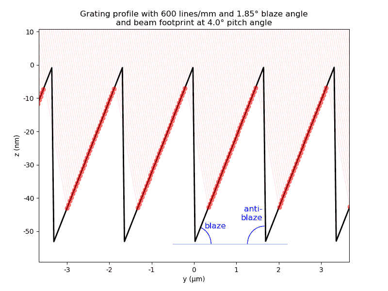
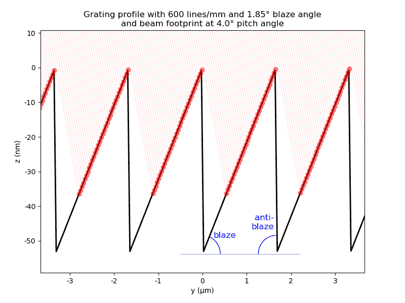
- __init__(*args, **kwargs)
- blaze, antiblaze: float
Angles in radians
- rho: float
Nominal line density in inverse mm.
- targetE: None or (energy, order[, cff])
Reference energy in eV and diffraction order. The optional cff fixes nominal angles and aligns the pitch when
pitch='auto'.- propagationMode: ‘wave’ or ‘rays’
Selects the physical groove profile used for wave propagation or the idealized macroscopic grating used for ray propagation. The backward-compatible default is ‘wave’.
- class xrt.backends.raycing.oes.LaminarGrating(OE)
Grating of rectangular profile.
- class xrt.backends.raycing.oes.VLSLaminarGrating(OE)
Grating of rectangular profile with variable period.
- __init__(*args, **kwargs)
- rho: float
Nominal groove density in inverse mm. In the direct convention it is the same value as
coeffs[0].- coeffs: sequence
In the normalized convention,
[P0, P1, ...]definesrho(y) = rho * (P0 + 2*P1*y + 3*P2*y**2 + ...). In the direct convention,[a0, a1, ...]definesrho(y) = a0 + a1*y + a2*y**2 + ....- coefficientConvention: ‘normalized’ or ‘direct’
Selects the meaning of coeffs. The default is ‘normalized’ for compatibility. Switching conventions keeps rho unchanged; if normalized P0 is not 1, switching to ‘direct’ sets a0 to rho and changes the constant term of the density polynomial.
- targetE: None or (energy, order[, cff])
Reference energy in eV and diffraction order. The optional cff fixes nominal incidence and diffraction angles, and aligns the pitch when
pitch='auto'.- aspect: float
Top-to-period ratio of the groove.
- depth: float
Depth of the groove in mm.
An explicit gratingDensity is also accepted in the normalized
OEformat['y', rho, P0, ...]. It takes precedence over rho and coeffs at initialization.- propagationMode: ‘wave’ or ‘rays’
Selects the physical groove profile used for wave propagation or the idealized macroscopic grating used for ray propagation. The backward-compatible default is ‘wave’.
- class xrt.backends.raycing.oes.MeshOE(OE)
Optical element defined by an STL mesh.
- __init__(*args, **kwargs)
The top surface is the connected, uppermost set of triangles whose unit normals have a significant z-component, regardless of triangle winding. The corresponding vertices are extracted and used to reconstruct a continuous surface z = f(x, y).
The fitted surface uses independent X/Y conic profiles. Matching parabolic hints include the quadratic cross term; matching circular hints use an exact torus; matching elliptical hints use a biconic. Different hints use additive profiles without cross terms.
- fileName: str
Path to the STL file.
- orientation: str
Axis-remapping string for converting STL coordinates into the xrt coordinate system. (X right-left, Y forward-backward, Z top-down). Default ‘XYZ’.
- recenter: bool
If True, the mesh is recentered so that the local origin corresponds to the geometric center of the top surface of the optical element.
- surfaceHintX: str
Sagittal (X) profile: ‘flat’, ‘parabolic’, ‘circular’, or ‘elliptical’. Default ‘parabolic’. ‘spline’ selects 2D cubic interpolation and sets both axis hints to ‘spline’.
- surfaceHintY: str
Meridional (Y) profile: ‘flat’, ‘parabolic’, ‘circular’, or ‘elliptical’. Default ‘parabolic’. ‘spline’ selects 2D cubic interpolation and sets both axis hints to ‘spline’.
Diagnostics: RsagFit and RmerFit are fitted vertex radii in mm (infinite for flat axes). conicXFit and conicYFit are fitted conic constants. fitRmsError is the RMS height residual in micrometres, evaluated at the selected, unique STL surface vertices.
Distorted surfaces
For introducing an error to an ideal surface you must define two methods in
your descendant of the OE: local_z_distorted (or
local_r_distorted for a parametric surface) and local_n_distorted. The
latter method returns two angles d_pitch and d_roll or a 3D vector that will be
added to the local normal. See the docstrings of OE.local_n_distorted()
and the example ‘Defocusing by a distorted mirror’.