Notes on using xrtGlow
3D glasses button is a two-state button. When it is pressed, xrtGlow will update its view whenever changes are made to the beamline in xrtQook. If you close the window of xrtGlow and the button is pressed, xrtGlow will pop up again after any change in xrtQook. To really close xrtGlow, deactivate the button.
You can use the CTRL-F1 shortcut to open xrtGlow, F4 to dock/undock it into/from the xrtQook window.
The Navigation panel of xrtGlow has several columns. The last columns may be hidden in the initial view. You can access them by enlarging the window.
The element will appear on the Navigation panel only if interacts with the beam, i.e. has an assigned method returning Beams.
Export to Image is available under the context menu -> File. You can save and load the scene settings (camera position, model orientation, rays opacity and so on) as well.
Load the example …/examples/withRaycing/_QookBeamlines/lens3.xml and follow the instructions in Description tab in order to understand the visualization precision vs the swiftness of the 3D manipulations.
From xrtGlow, press F1 to see the available keyboard shortcuts. Also observe the available pop-up menu by right mouse click.
Movements of the model are separated for the transverse plane and longitudinal direction. Use SHIFT-MouseLeft and ALT-MouseLeft for corresponding movements.
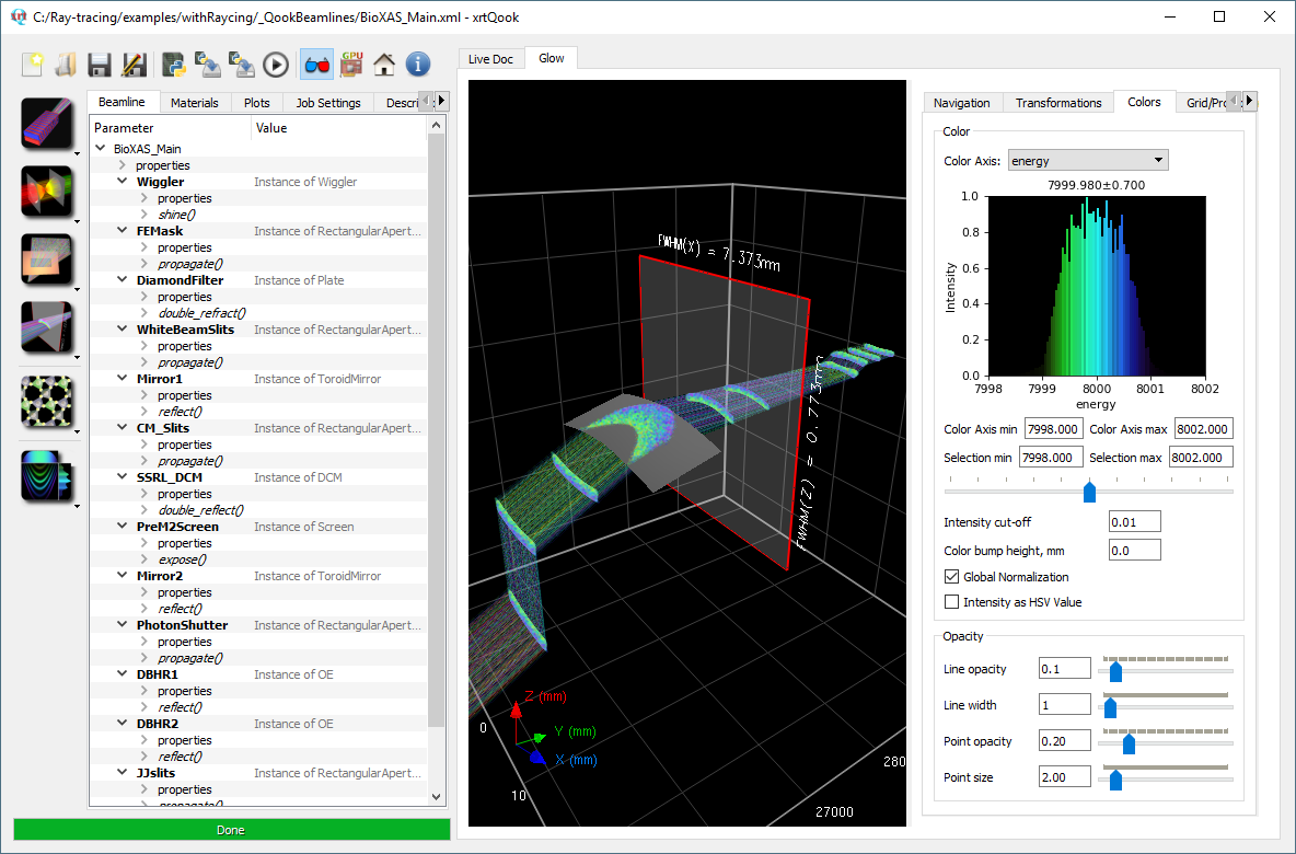
The color histogram without Virtual Screen shows the color map – the correspondence between the selected physical parameter (e.g. energy) and the colors. With Virtual Screen active (by F3), the plot shows a histogram of the selected parameter as distributed on Virtual Screen. In both cases the user may select a sub-band on the color plot by the mouse. The vertical extent in that selection is irrelevant.
Virtual Screen is instantiated on the Beam as close as possible to the center of the window. There are several ways to move it:
Holding CTRL-MouseLeft: moves the Virtual Screen along the Beam.
CTRL-SHIFT-MouseLeft and CTRL-ALT-MouseLeft: moves the whole beamline through the fixed Virtual Screen in transverse or longitudinal directions correspondingly.
If color gradients overlap on the Virtual Screen it can be useful to expand the color axis in real space by enabling the Color Bump. Do not forget that the resulting height distribution is artificial, does not present the real intersections of rays and is only used for convenience.
Rays or footprints visualisation can be enabled/disabled either by setting corresponding checkboxes in the Navigation Panel for individual elements or globally by changing the opacity of the lines and points in the Color Panel. The same applies for the Projections.
Intensity cut-off allows to omit the visualisation of the darkest/weakest rays. It is especially important if Intensity defines the Value key in HSV color space when dark rays can shadow the whole beam.

A convenient way to inspect a detailed beam footprint on the coordinate grid is to use Projections: disable the Perspective, select only the footprint of interest on the Navigation Panel (or disable all and just leave the Virtual Screen on), enable the projection, set to zero the Projection Line Opacity (or Line Width, it will do the job too), increase the Projection Point Opacity to improve the visibility, enable the Fine Grid. Increase the number of rays in the source if necessary.

If you have any doubts regarding the orientation of the optical element or trying to identify the directions, you can plot local coordinate axes by checking the corresponding option on the Scene panel or in the context menu. Make sure that the surface rendering is enabled for this element on the Navigation panel. Orientation of the diffraction planes will be represented by the yellow arrow in case of the crystals with asymmetric cut.
Depth test is disabled by default for the Points. Enable it if you do not want the footprints to shine through solid surfaces of the optical elements. Be aware that the Points may be obscured by rays in this case.

Scene checkbox ‘Virtual Screen for Indexing’ can be used to filter the rays hitting the Virtual Screen. This is convenient for retrospective analysis, to highlight the rays of the initial beam that reach the final point.
Antialiasing can improve the visual quality of the scene, but it seriously affects the performance (depending on the number of rays / elements in the model), only enable it after all modifications to the scene are applied, prior the Export to file. Nevertheless antialiasing is always enabled for the coordinate grid.
Default Zoom does not involve the coordinate grid, if you want to Zoom In/Out the whole scene, use CTRL-MouseWheel.