xrt (XRayTracer)
- DOI:
- GitHub:
- PyPI:
- License:
- Authors:
Konstantin Klementiev (MAX IV Laboratory), Roman Chernikov (Canadian Light Source)
Package xrt is a python software library for ray tracing and wave propagation in x-ray regime. It is primarily meant for modeling synchrotron sources, beamlines and beamline elements. Includes a GUI for creating a beamline and interactively viewing it in 3D.
Vortex beam with l=1 and p=1. Colored by phase. Vortex beam with l=1 and p=1. Colored by phase. |
GUIs
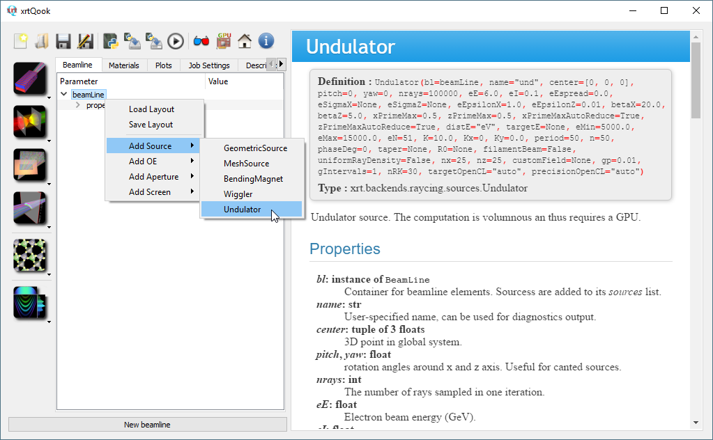
xrtQook – a GUI for creating a beamline
The main interface to xrt is through a python script. Many examples of such scripts can be found in the supplied folders examples and tests. The script imports the modules of xrt, instantiates beamline parts, such as synchrotron or geometric sources, various optical elements, apertures and screens, specifies required materials for reflection, refraction or diffraction, defines plots and sets job parameters.
The Qt tool xrtQook takes these ingredients as GUI elements and prepares
a ready to use script that can be run within the tool itself or in an external
Python context. xrtQook has a parallelly updated help panel that
provides a complete list of parameters for the used objects. xrtQook
writes/reads the recipes of beamlines into/from xml files.
In the present version, xrtQook does not provide automated generation of
scans and does not create wave propagation sequences. For these two tasks,
the corresponding script parts have to be written manually based on the
supplied examples and the present documentation.
See a brief tutorial for xrtQook.
 A view of xrtQook with an empty beamline tree on the left and a
help panel on the right. A view of xrtQook with an empty beamline tree on the left and a
help panel on the right.
A view of xrtQook with an empty beamline tree on the left and a
help panel on the right. A view of xrtQook with an empty beamline tree on the left and a
help panel on the right.xrtGlow – an interactive 3D beamline viewer
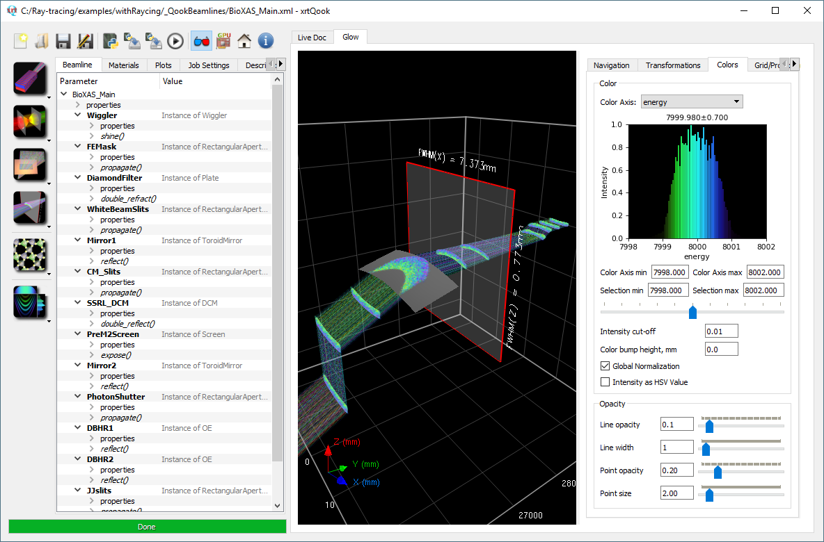
The beamline created in xrtQook or in a python script can be interactively viewed in an OpenGL based widget xrtGlow. It visualizes beams, footprints, surfaces, apertures and screens. The brightness represents intensity and the color represents an auxiliary user-selected distribution, typically energy. A virtual screen can be put at any position and dragged by mouse with simultaneous observation of the beam distribution on it. See two example screenshots below (click to expand and read the captions).
The primary purpose of xrtGlow is to demonstrate the alignment correctness given the fact that xrtQook can automatically calculate several positional and angular parameters.
See aslo Notes on using xrtGlow.
xrtBentXtal – a GUI for bent crystal calculations
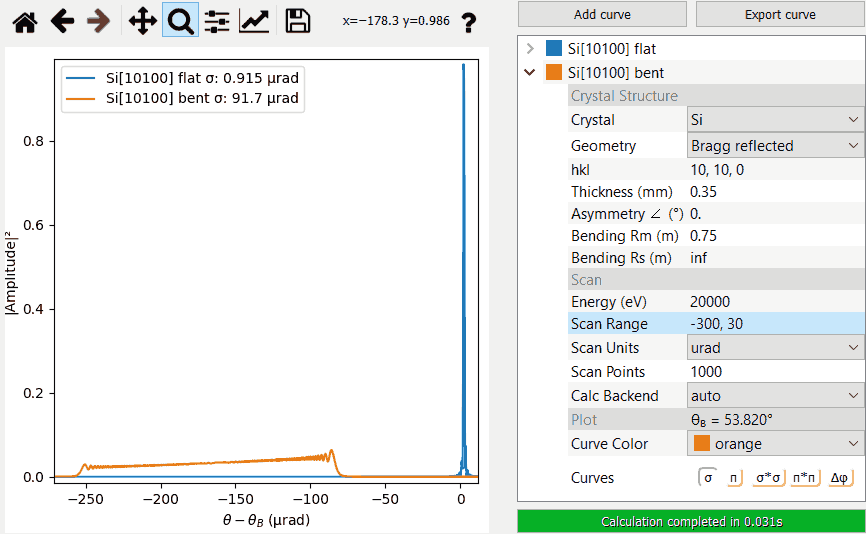
In addition to ray tracing applications with perfect and bent crystals, xrt has a GUI widget xrtBentXtal to calculate reflectivity curves of bent crystals with utilizing the power of modern GPUs. One can use this widget to conveniently study the influence of crystal type, bending radius, asymmetry angle, thickness and other parameters on reflectivity and compare multiple curves side by side. We include the CPU-based PyTTE code [PyTTE1] [PyTTE2] for reference and performance comparison. We also add the possibility to calculate transmitted amplitudes in Bragg geometry, missing in the original PyTTE, though this mode only works for CPU-based calculations and is not suitable for ray tracing due to memory constraints.
 xrtBentXtal -- a Qt widget for bent crystal calculations in xrt.
Shown are two reflectivity curves for a flat version of Si (10, 10, 0)
crystal (blue) and a bent version of it (orange). In going to higher
order reflexes the difference in the width of the reflection domain
becomes increasingly pronounced. xrtBentXtal -- a Qt widget for bent crystal calculations in xrt.
Shown are two reflectivity curves for a flat version of Si (10, 10, 0)
crystal (blue) and a bent version of it (orange). In going to higher
order reflexes the difference in the width of the reflection domain
becomes increasingly pronounced.
xrtBentXtal -- a Qt widget for bent crystal calculations in xrt.
Shown are two reflectivity curves for a flat version of Si (10, 10, 0)
crystal (blue) and a bent version of it (orange). In going to higher
order reflexes the difference in the width of the reflection domain
becomes increasingly pronounced. xrtBentXtal -- a Qt widget for bent crystal calculations in xrt.
Shown are two reflectivity curves for a flat version of Si (10, 10, 0)
crystal (blue) and a bent version of it (orange). In going to higher
order reflexes the difference in the width of the reflection domain
becomes increasingly pronounced.Features of xrt
Rays and waves. Classical ray tracing and wave propagation via Kirchhoff integrals, also freely intermixed. No further approximations, such as thin lens or paraxial. The optical surfaces may have figure errors, analytical or measured. In wave propagation, partially coherent radiation is treated by incoherent addition of coherently diffracted fields generated per electron. Propagation of individual coherent source modes is possible as waves, hybrid waves (i.e. partially as rays and then as waves) and only rays.
Publication quality graphics. 1D and 2D position histograms are simultaneously coded by hue and brightness. Typically, colors represent energy and brightness represents beam intensity. The user may select other quantities to be encoded by colors: angular and positional distributions, various polarization properties, beam categories, number of reflections, incidence angle etc. Brightness can also encode partial flux for a selected polarization and incident or absorbed power. Publication quality plots are provided by matplotlib with image formats PNG, PostScript, PDF and SVG.
Unlimited number of rays. The colored histograms are cumulative. The accumulation can be stopped and resumed.
Parallel execution. xrt can be run in parallel in several threads or processes (can be opted), which accelerates the execution on multi-core computers. Alternatively, xrt can use the power of GPUs via OpenCL for running special tasks such as the calculation of an undulator source or performing wave propagation.
Scripting in Python. xrt can be run within Python scripts to generate a series of images under changing geometrical or physical parameters. The image brightness and 1D histograms can be normalized to the global maximum throughout the series.
Synchrotron sources. Bending magnet, wiggler, undulator and elliptic undulator are calculated internally within xrt. Please look the section Comparison of synchrotron source codes for the comparison with other popular codes. If the photon source is one of the synchrotron sources, the total flux in the beam is reported not just in number of rays but in physical units of ph/s. The total power or absorbed power can be opted instead of flux and is reported in W. The power density can be visualized by isolines. The magnetic gap of undulators can be tapered. Undulators can be calculated in near field. Custom magnetic field is also possible. Undulators can be calculated on GPU, with a high gain in computation speed, which is important for tapering and near field calculations.
Shapes. There are several predefined shapes of optical elements implemented as python classes. The python inheritance mechanism simplifies creation of other shapes: the user specifies methods for surface height and surface normal. The surface and the normal are defined either in local Cartesian coordinates or in user-defined parametric coordinates. Parametric representation enables closed shapes such as capillaries or wave guides. It also enables exact solutions for complex shapes (e.g. a logarithmic spiral or an ellipsoid) without any expansion. The methods of finding the intersections of rays with the surface are very robust and can cope with pathological cases such as sharp surface kinks. Notice that the search for intersection points does not involve any approximation and has only numerical inaccuracy which is set by default as 1 fm. Any surface can be combined with a (differently and variably oriented) crystal structure and/or (variable) grating vector. Surfaces can be faceted.
Energy dispersive elements. Implemented are
crystals in dynamical
diffraction
, gratings (also with efficiency calculations), Fresnel zone plates, Bragg-Fresnel optics andmultilayers in dynamical diffraction. Crystals can work in Bragg or Laue cases, in reflection or in transmission. The two-field polarization phenomena are fully preserved, also within the Darwin diffraction plateau, thus enabling the ray tracing of crystal-based phase retarders.Materials. The material properties are incorporated using
three
different tabulations
of the scattering factors, with differently wide and differently dense energy meshes. Refractive index and absorption coefficient are calculated from the scattering factors. Two-surface bodies, such as plates or refractive lenses, are treated with both refraction and absorption.Multiple reflections. xrt can trace multiple reflections in a single optical element. This is useful, for example in ‘whispering gallery’ optics or in Montel or Wolter mirrors.
Non-sequential optics. xrt can trace non-sequential optics where different parts of the incoming beam meet different surfaces. Examples of such optics are poly-capillaries and Wolter mirrors.
Singular optics. xrt correctly propagates vortex beams, which can be used for studying the creation of vortex beams by transmissive or reflective optics.
Global coordinate system. The optical elements are positioned in a global coordinate system. This is convenient for modeling a real synchrotron beamline. The coordinates in this system can be directly taken from a CAD library. The optical surfaces are defined in their local systems for the user’s convenience.
Beam categories. xrt discriminates rays by several categories: good, out, over and dead. This distinction simplifies the adjustment of entrance and exit slits. An alarm is triggered if the fraction of dead rays exceeds a specified level.
Portability. xrt runs on Windows and Unix-like platforms, wherever you can run python.
Examples. xrt comes with many examples. See the galleries, the links are at the top bar.
Tests. xrt comes with the tests of its several main aspects. See the folder tests and also this documentation for the tests of undulators, optical elements, materials and wave propagation.
Dependencies
numpy, scipy and matplotlib are required. If you use OpenCL for calculations on
GPU or CPU, you need AMD/NVIDIA drivers, Intel CPU only OpenCL runtime
(these are search key words), pytools and pyopencl. PyQt4 or PyQt5 are needed
for xrtQook. Spyder (as library of Spyder IDE) is highly recommended for nicer
view of xrtQook. OpenGL is required for xrtGlow.
Get xrt
xrt is available as source distribution from pypi.python.org and from GitHub. The distribution archive also includes tests and examples. The complete documentation is available online on Read the Docs and offline as zip file on GitHub.
Installation
Unzip the .zip file into a suitable directory and use
sys.path.append(path-to-xrt) in your script. You can also install xrt to the
standard location by running python setup.py install from the directory
where you have unzipped the archive, which is less convenient if you try
different versions of xrt and/or different versions of python. Note that
python-64-bit is by ~20% faster than the 32-bit version (tested with
WinPython). Also consider Speed tests for making choice between
Windows and Linux and between Python 2 and Python 3.
Get help
For getting help and/or reporting a bug please use GitHub xrt Issues.
Citing xrt
Please cite xrt as: K. Klementiev and R. Chernikov, “Powerful scriptable ray tracing package xrt”, Proc. SPIE 9209, Advances in Computational Methods for X-Ray Optics III, 92090A (2014); doi:10.1117/12.2061400. Online documentation on xrt.readthedocs.io; doi:10.5281/zenodo.1252468.
For the new capabilities: 1) Calculations of elastically deformed crystals on GPUs, 2) Mode analysis and mode propagation, 3) Modelling OAM (Orbital Angular Momentum) beams, please cite: K. Klementiev & R. Chernikov, “New Features of xrt: Bent Crystals, Coherent Modes, Waves with OAM” Synchrotron Radiation News (2023) 36:5, 23-27; doi:10.1080/08940886.2023.2274735.
Acknowledgments
Josep Nicolás and Jordi Juanhuix (synchrotron Alba) are acknowledged for discussion and for their Matlab codes used as examples at early stages of the project.
Andrew Geondzhian and Victoria Kabanova (summer students at DESY) are acknowledged for their help in coding the classes of synchrotron sources.
Rami Sankari and Alexei Preobrajenski (MAX IV Laboratory) are thanked for discussion, testing and comparing with external codes.
Hasan Yavaş, Jozef Bednarčik, Dmitri Novikov and Alexey Zozulya (DESY Photon Science) are acknowledged for supplied cases.
Hamed Tarawneh (MAX IV Laboratory) has initiated the custom field undulator project and supplied tables of magnetic field.
Bernard Kozioziemski (LLNL) has pointed to the importance of considering the total absorption cross-section (not just photoelectric absorption) in the cases of light materials at high energy. He also did deep tests of the mosaic crystal model.
Emilio Heredia (CLS) is thanked for valuable suggestions on GUI.
Tim May (CLS) is acknowledged for inspiring the custom magnetic field calculation development, providing field tables and comparing the results with other codes.
Louisa Pickworth (MAX IV Laboratory) has provided curves from other codes for testing reflectivity/transmittivity of multilayers.
User’s Guide
- Using xrt
- Using xrtQook for script generation
- Using custom optical elements in xrtQook
- Notes on using xrtGlow
- Using xrt as x-ray calculator
- Raycing backend
- Shadow backend
- Customizing your plots
- Controlling ray tracing execution
- Calculations on GPU
- Gallery of plots and scripts 1. Synchrotron sources
- Gallery of plots and scripts 2. X-ray optics
- Gallery of plots and scripts 3. Wave propagation
- Logo
- Speed tests
- The MIT License


